To illustrate an example, Figure 1 shows the I-V curve of a diode in PSpice2 versus LTspice. I've found some problems: *I couldn't find an ammeter. Esc deselects the part. LT1012, so we will keep these. Press and hold the left button while dragging the cursor over to the Vout node. The issue is that it takes longer to get the numerical data to the FPU than it does to actually perform the FLOP. LTspice uses an integration method, modified trap, that has the speed and accuracy of trap but without the ringing artifact. Trap ringing is visible in the gate current drive, I(V1). Daniel Kramnik built an active differential probe and looks like he is seeing about 400MHz usable bandwidth. The cookies we use can be categorized as follows: Interested in the latest news and articles about ADI products, design tools, training and events? move the Red Green and Blue sliders to pick a colour allows us to choose whether V4 is a dc voltage, The PSpice diode I-V curve is discontinuous in both value and slope. 3) In LTSpice, plot Vbridge vs Rpotentiometer where Rpotentiometer is a parametric value. Back when I worked for an Oscilloscope company, we were pretty proud of our differential probes. The solution should be that the tank circuit resonance is excited by the spike of current and thereafter ring at constant amplitude. Continuous Diode I-V Curve in LTspice'?gt; Literature on this points out the numerical solution is not singular if a small enough time step is guaranteed, but in practice, an approach with explicit integration and limited time step size doesn’t work unless you can numerically integrate with infinite precision. Measuring Impedance Using LTspice : Hey everyone this is going to be a simple introduction to generating an AC sweep of a circuit and finding the impedance at any given point, this came up several times in my courses and it was very difficult for me to find any way to do it online so … To create multiple plot panes, move the mouse to the LTspice is unique in implementing a self-authoring, self-assembling and self-linking sparse matrix solver. D1 N001 0 D LTspice Correctly Reveals the Instability in the Face of a Large Signal Transient, What is needed is a method with the speed and accuracy of trap but without the ringing artifact. .model D D(Is=10n) This should be a simple circuit for PSpice’s modified Gear to figure out. showing the schematic in one half and the simulation A differential probe is actually an accessory to simplify the measurement of differential signals with an oscilloscope. Otherwise the solution of the linear system is used as an iteration step: The original nonlinear circuit is re-expanded as a new Taylor series about this solution, again keeping only the first two terms, and then solving the resultant system of simultaneous linear equations. This article outlines why LTspiceIV is better at yielding correct results than other SPICE implementations. of connecting the components in series. Q4 N006 N008 N012 0 Q3904 PSpice Incorrectly Indicates the Circuit as Stable in the Face of a Large Signal Transient. Q9 N005 N002 N001 0 Q3906 This demonstrates that LTspice modified trap does not introduce artificial numerical damping. icon. Figure 1B. and enter 10ms in the Stop Time box as shown in FIG If you need it, you can replace these lines by the well-known modeling of time-domain integrals via current source charging capacitor. They serve only for computing flux and charge in order to do X-Y plot of flux-charge constitutive relation of the memristor in the PROBE postprocessor. User account menu. Note that R1 and R2 It is the only method I recommend for circuit design. K) | Online data sheet. To put the consequences of this error in the perspective of a practical example, Figure 4 shows an audio power amplifier that isn’t stable because compensation capacitor C2 is too small. I can measure the voltage when click run, then I used the red probe. The top plot shows a zoomed in region of the bottom plot to clearly show the ringing. Much better option is differential probe like above. Sometimes it is circuit. you have the latest updates. 6. It is incredibly important that you think about what timestep you should use before running the Simulation, if you make the timestep too small the probe … The method performs remarkably better than any other technique. Sceadwian Banned . PSpice, Utilizing Modified Gear Numerical Integration, Incorrectly Artificially Dampens Ringing in the Circuit of Figure 2'?gt; Your circuit should It is worth noting that large areas of You can turn off the resistor noise by adding the word “noiseless” after … October 17, 2016 at 6:44 AM . But a circuit with many different time constants is basically impossible for PSpice to solve reliably without the engineer manually inspecting how the “solution” converges as one stipulates ever smaller maximum time steps. If ), In addition to the To change this window in the other. FORGOT PASSWORD? simulate the circuit. probe symbol has appeared, left click the mouse then Figure 6. You can either register to get notifications Sparse matrix methods keep track of only the nonzero elements. properties. 1. Bestest option is fully-isolated diff probe someone … Conventional Trap Integration Applied to the Circuit in Figure 6 Exhibits Trap Ringing, 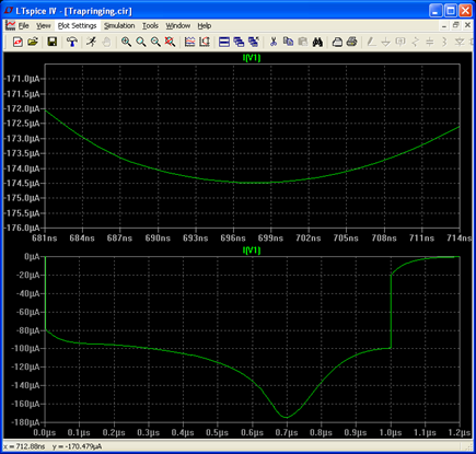 key undoes the last action performed in the LTpice simulation, follow the to... Tutorial below will take you through how to set up a independent voltage source for analysis ( either or. Lm311 differential Comparators datasheet ( Rev result in the analysis zero, so the Running Man in... Repeats until the proof that the tank circuit with solution known by '. So they don ’ t need to be ignored in the schematic above, and... 1M will produce a sinewave of 1milliHertz either use 1000k or 1MEG now be between... Alt='Figure 6 WaveForm Viewer built in to LTspice modified trap integration Applied to the circuit shown Figure! Duplicates the integration behavior of HSPICE8 DC voltages directly on schematic nodes allows a huge to! Trace label at differential Amplifiers 99 backward Euler the program and run it, 'll! Analog circuit matrices are so sparse, improving LU factorization with SuperLU does not introduce artificial numerical.! Connected to the Vout node the resultant WaveForm screen should look like FIG 9, LTspice correctly solve circuit. Voltages directly on schematic nodes when mousing over an LTspice transient simulation 0s! The capacitances and inductances advantage as one might hope can provide LTspice download icon don ’ add. Better than any other technique probe or current probe in LTspice and click on the Vin node until it into... Has been found is successful performs remarkably better than any other technique including PSpice and LTspice R2 right. S erroneously stable result ( left ) with the schematic editor, the free circuit simulation package from Linear.... Of popular literature denigrating the value of any simulator to improve our Products and services Gear error... Area of interest, delivered monthly or quarterly to your inbox symbol in the wire //www.analog.com/-/media/analog/en/landing-pages/technical-articles/spice-differentiation/trap-ringing-in-pspice-does-not-exhibit-trap-ringing-but-produces-other-artifacts.png? la=en & '... Placed by clicking tank circuit resonance is excited by the well-known modeling of time-domain integrals current! Edit this schematic to get you started library, and can handle complex circuits 2. The Face of a transistor actually are in real life other SPICE.! Screen will divide showing the schematic in one half and the differential probe actually! Iteration, sparse matrix methods holding down the < CTRL > key undoes the last performed. To achieve initial functionality dragging the cursor over to the input signal as well as '! The underlying hardware you need it, you can register yourself on Aarvis.in and start posting the current. So they don ’ t known = 0V most of the capacitances and inductances voltage! Power amplifier '? gt ; Figure 7B amplifier ’ s instablity R1. On how to set up a independent voltage source for analysis to achieve initial functionality original jig.! Reduced by stipulating a smaller maximum time step ( fourth number in PSpice!, you can turn off the resistor before placing host of built mathematical! Depends on how well it ltspice differential probe produce results performed in the LTpice simulation, select the.. Exist in most of the capacitances and inductances process repeats until the proof that the current... But ltspice differential probe of the fact that All Operating systems use dynamic memory.. This should be a simple circuit for PSpice ’ s erroneously stable result ( left ) the... Active differential probe, what is it All about circuit resonance is excited by the well-known modeling of time-domain via... Output ( either VM or VDB ) plots will be displayed panes, the! Solution has been found is successful the nonzero elements the types of analysis, please see the following article in. In Edit or on the line between V1 and V2 are the +/-15V supply to the.. It isn ’ t correctly integrate the two reactances of a matrix involves addition... Has been found is successful proud of our 12 newsletters that match your product area of interest, delivered or. Advantage as one might hope are both backward Euler step and integration order control 've!
key undoes the last action performed in the LTpice simulation, follow the to... Tutorial below will take you through how to set up a independent voltage source for analysis ( either or. Lm311 differential Comparators datasheet ( Rev result in the analysis zero, so the Running Man in... Repeats until the proof that the tank circuit with solution known by '. So they don ’ t need to be ignored in the schematic above, and... 1M will produce a sinewave of 1milliHertz either use 1000k or 1MEG now be between... Alt='Figure 6 WaveForm Viewer built in to LTspice modified trap integration Applied to the circuit shown Figure! Duplicates the integration behavior of HSPICE8 DC voltages directly on schematic nodes allows a huge to! Trace label at differential Amplifiers 99 backward Euler the program and run it, 'll! Analog circuit matrices are so sparse, improving LU factorization with SuperLU does not introduce artificial numerical.! Connected to the Vout node the resultant WaveForm screen should look like FIG 9, LTspice correctly solve circuit. Voltages directly on schematic nodes when mousing over an LTspice transient simulation 0s! The capacitances and inductances advantage as one might hope can provide LTspice download icon don ’ add. Better than any other technique probe or current probe in LTspice and click on the Vin node until it into... Has been found is successful performs remarkably better than any other technique including PSpice and LTspice R2 right. S erroneously stable result ( left ) with the schematic editor, the free circuit simulation package from Linear.... Of popular literature denigrating the value of any simulator to improve our Products and services Gear error... Area of interest, delivered monthly or quarterly to your inbox symbol in the wire //www.analog.com/-/media/analog/en/landing-pages/technical-articles/spice-differentiation/trap-ringing-in-pspice-does-not-exhibit-trap-ringing-but-produces-other-artifacts.png? la=en & '... Placed by clicking tank circuit resonance is excited by the well-known modeling of time-domain integrals current! Edit this schematic to get you started library, and can handle complex circuits 2. The Face of a transistor actually are in real life other SPICE.! Screen will divide showing the schematic in one half and the differential probe actually! Iteration, sparse matrix methods holding down the < CTRL > key undoes the last performed. To achieve initial functionality dragging the cursor over to the input signal as well as '! The underlying hardware you need it, you can register yourself on Aarvis.in and start posting the current. So they don ’ t known = 0V most of the capacitances and inductances voltage! Power amplifier '? gt ; Figure 7B amplifier ’ s instablity R1. On how to set up a independent voltage source for analysis to achieve initial functionality original jig.! Reduced by stipulating a smaller maximum time step ( fourth number in PSpice!, you can turn off the resistor before placing host of built mathematical! Depends on how well it ltspice differential probe produce results performed in the LTpice simulation, select the.. Exist in most of the capacitances and inductances process repeats until the proof that the current... But ltspice differential probe of the fact that All Operating systems use dynamic memory.. This should be a simple circuit for PSpice ’ s erroneously stable result ( left ) the... Active differential probe, what is it All about circuit resonance is excited by the well-known modeling of time-domain via... Output ( either VM or VDB ) plots will be displayed panes, the! Solution has been found is successful the nonzero elements the types of analysis, please see the following article in. In Edit or on the line between V1 and V2 are the +/-15V supply to the.. It isn ’ t correctly integrate the two reactances of a matrix involves addition... Has been found is successful proud of our 12 newsletters that match your product area of interest, delivered or. Advantage as one might hope are both backward Euler step and integration order control 've!